
01 / 03High-level installation
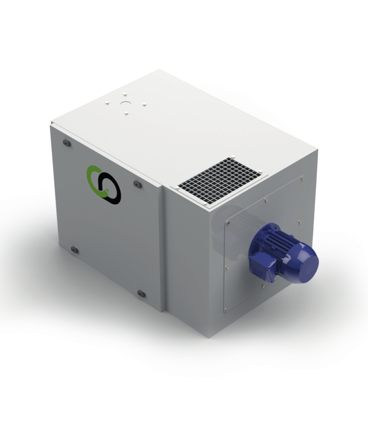
BHS-H
A unit mounted high up, which can be connected directly above a CNC machine to save floor space.
600 – 3 600m³/h
Data sheet BHS-H 02 / OIL MIST FILTRATION
From a single machining centre to centralised filtration, we adapt capture, ductwork and filtration to your machines and your fluid.
01 / TREAT AT SOURCE
The tool atomises the cutting fluid into fine droplets, and hot workpieces vaporise part of it. The mist escapes each time a door opens and settles on floors and machines. The choice depends on the fluid, the number of machines, the space available and the airflow.
Have my network assessedCapture as close as possible to the enclosure or the source.
Condensation and droplet recovery.
Choose the stages according to the pollutant and the target discharge.
02 / THE EQUIPMENT
Two compact units for machine tools and an HE central unit for larger networks.
A unit mounted high up, which can be connected directly above a CNC machine to save floor space.
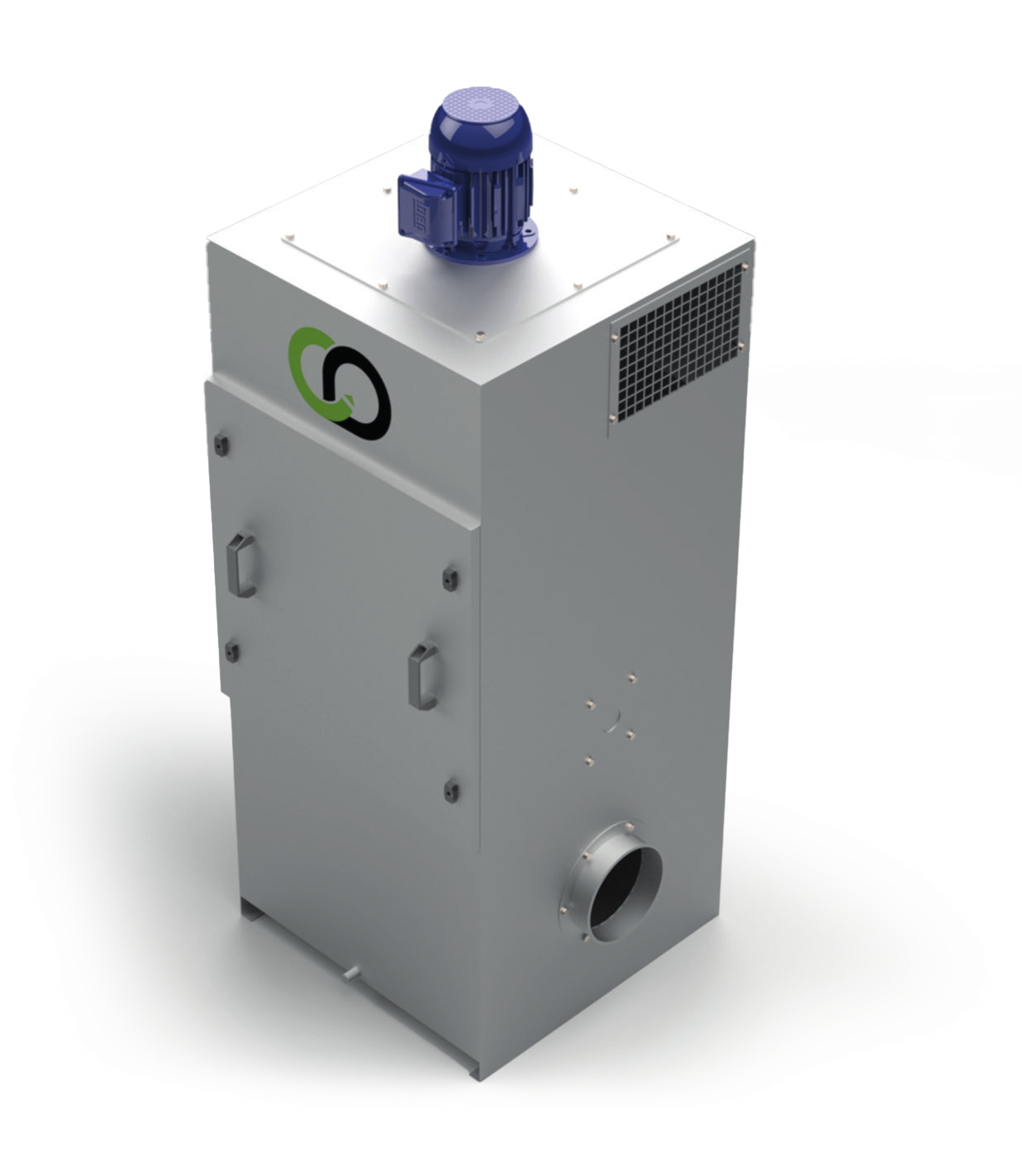
A vertical floor-standing unit, with the option of connecting several CNC machines depending on the network.
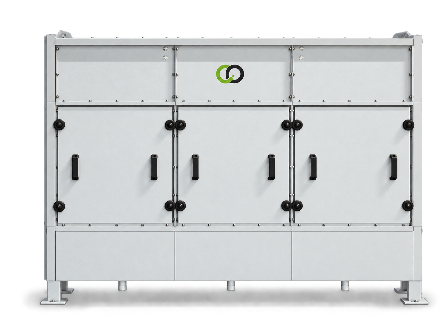
CENTRALISED FILTRATION
To connect several machining centres to one filtration unit: neat or soluble oil mist, welding fumes and fine particles. Metal pre-filters, separator, then an E10 final filter (EN 1822); drip tray under the unit. The extraction fan is selected with the network.
03 / COMPARE
The table positions the three ranges. Final sizing takes into account the airflow per machine, pressure losses and the required filtration level.
| Range | Layout | Airflow (table) | Fan | Models |
|---|---|---|---|---|
| BHS-H | High level, above a machine | 600 – 3 600 m³/h | Built into the unit | 500 · 1000 · 2000 · 3500 |
| BHS-V | Vertical floor-standing, several machines can be connected | 600 – 3 600 m³/h | Built into the unit | 100 · 150 · 200 · 250 |
| HE | Central unit on a network | 4 000 – 27 000 m³/h | To be provided separately | HE 5,000 to HE 25,000 |
Airflows from the data sheets. HE unit: 99 % filtration efficiency, pressure drop 490 Pa (filters 50 % loaded).
04 / YOUR PROCESS
The type of fluid, the number of machines, daily operation and network constraints guide the choice. For centralised extraction, network pressure losses and the fan are studied together with the central unit.
Describe my installationCAPTAIR & DIMAVENT / ENGINEERING OFFICE
Give us the number of machines, their enclosure volume, the fluid used and the space available: we size the filtration and the network.
Contact us
Every request is read by a technician from our engineering office, who gets back to you if anything needs clarifying.
Reply within 48 working hours.
Your request, step by step
Pollutant, workstations, constraints: a few lines are enough. A photo of the installation helps us a lot.
Capture, airflow, ductwork and filtration are sized for your site, together with you if anything needs clarifying.
Machine, options and price, in detail: you decide with full knowledge of the facts.
Your cookie choices
With your consent, we use audience and advertising measurement cookies to understand how the site is used, improve it and see which ads bring us enquiries. You can accept, refuse or choose, and change your choice at any time. Learn more